My old Gauss cannon CAD project
Posted: Thu Dec 03, 2009 11:19 pm
The first quarter of my freshman year at the Milwaukee School of Engineering (fall 1996) had me taking an Engineering Graphics course (CAD). I decided for the big project I'd take on the internal mechanics of the Gauss cannon from D2:
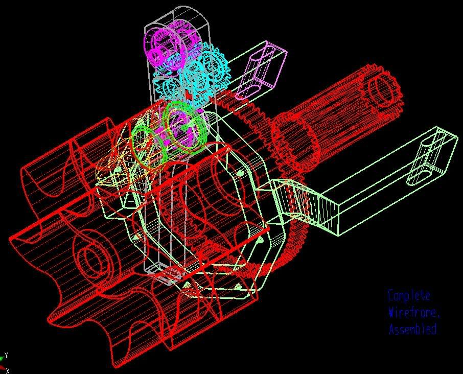
My conceptualization involved a central rotor that meshed with a gear turned by the ship, which scooped in the rounds fed in from above. Once fully loaded, a \"firing piston\", also powered by the ship in a reciprocal motion, would strike all 8 rounds at once. As the next central rotation commenced, two wheels would grab the spent shells and propel them out the side opposite where the new ones come in. I realized later I could probably take advantage of recoil, and it could have used some ball bearings, and I never got around to the outer housing, but after working on it for 60 hours and having 4 other classes, I could only finish so much.
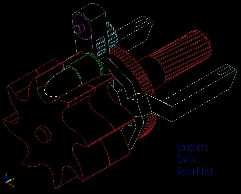
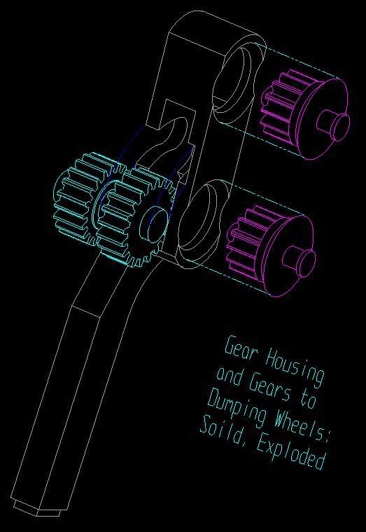
I kept the manufacturing process in mind, knowing that once each part was made, it would have to be assembled some way, and the exploded view reflects how the parts would fit together:
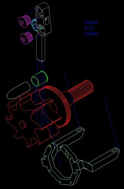
Some firing piston specs. Dimensions are in millimeters:
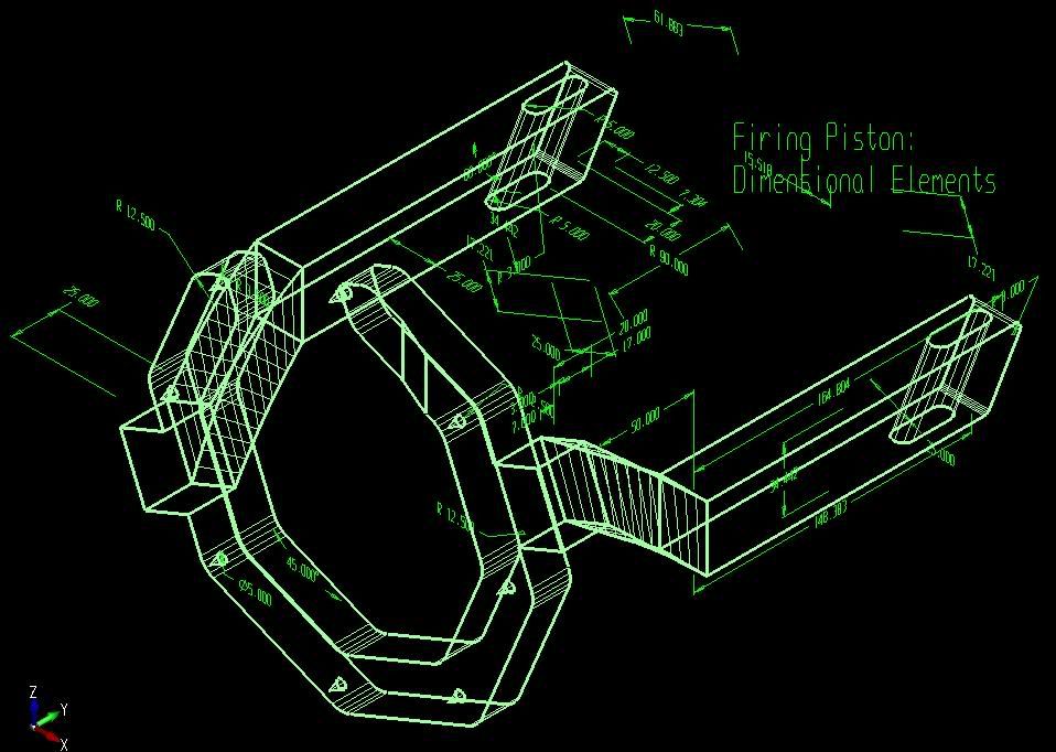
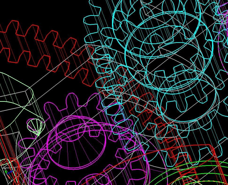
Gears were a challenge. Done right, there's 4 concentric circles and 8 arcs involved in drawing each tooth. In the second shot below, you can see the purple gear meshing perfectly with one of the blue gears:

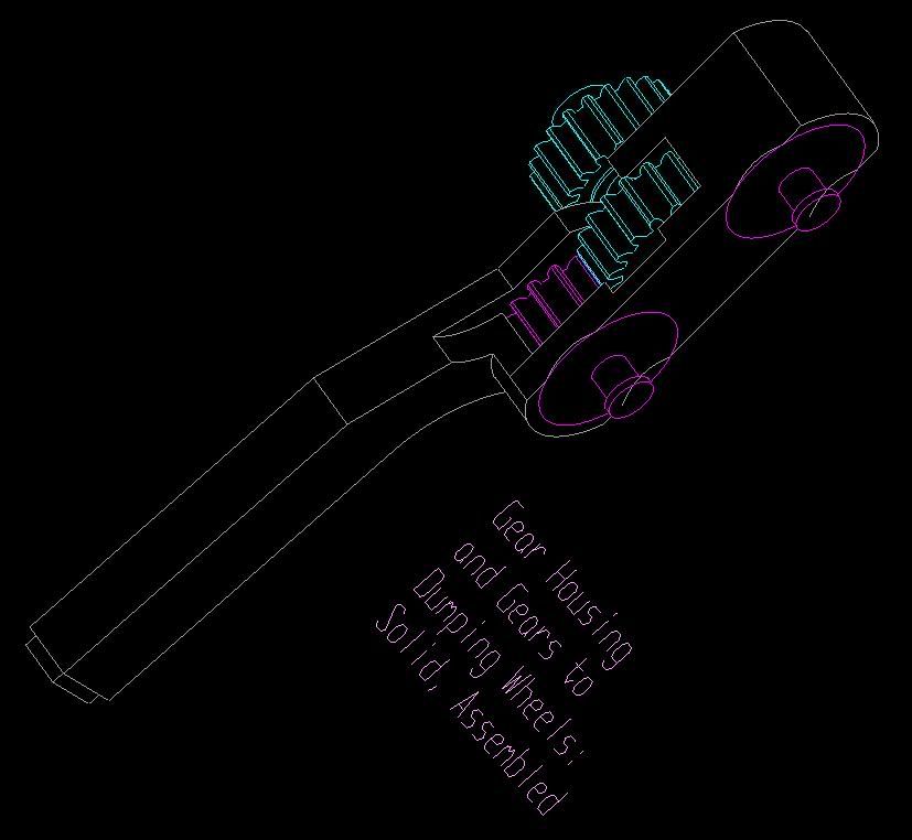
The housing for the \"dumping wheel\" gear drives:
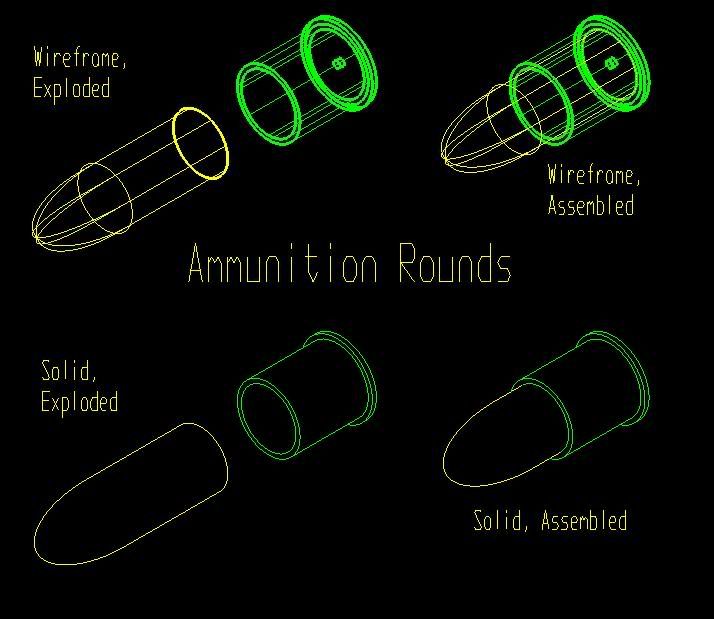
And of course, some ammunition close-ups for good measure:
I got an A in the class. I have Kubotek Spectrum Lite 9.0 to thank for helping me resurrect these 13-year-old PRT files. Hope you enjoyed them!

My conceptualization involved a central rotor that meshed with a gear turned by the ship, which scooped in the rounds fed in from above. Once fully loaded, a \"firing piston\", also powered by the ship in a reciprocal motion, would strike all 8 rounds at once. As the next central rotation commenced, two wheels would grab the spent shells and propel them out the side opposite where the new ones come in. I realized later I could probably take advantage of recoil, and it could have used some ball bearings, and I never got around to the outer housing, but after working on it for 60 hours and having 4 other classes, I could only finish so much.

I kept the manufacturing process in mind, knowing that once each part was made, it would have to be assembled some way, and the exploded view reflects how the parts would fit together:

Some firing piston specs. Dimensions are in millimeters:

Gears were a challenge. Done right, there's 4 concentric circles and 8 arcs involved in drawing each tooth. In the second shot below, you can see the purple gear meshing perfectly with one of the blue gears:


The housing for the \"dumping wheel\" gear drives:


And of course, some ammunition close-ups for good measure:

I got an A in the class. I have Kubotek Spectrum Lite 9.0 to thank for helping me resurrect these 13-year-old PRT files. Hope you enjoyed them!